EGPIO
Hardware
The OVMS has 10 general purpose I/O ports, provided by a MAX7317 I/O expander.
The MAX7317 ports can be individually configured as either an open-drain output, or an overvoltage-protected Schmitt input. Being open-drain, you need to add pull-up resistors for input and output switch uses to get a defined high level (e.g. 10K to 3.3V). See the datasheet for details on maximum current & voltage ratings.
Depending on your hardware configuration, up to 4 ports may be used by the module. 6 are generally free to use.
Port |
Signal(s) |
Exp.Pin |
Default usage |
|---|---|---|---|
0 |
MDM_EN |
15 |
Modem enable |
1 |
SW_CTL |
– |
Ext12V control (SW_12V) |
2 |
CAN1_EN + EIO_1 |
17 |
CAN1 transceiver enable |
3 |
MDM_DTR + EIO_2 |
19 |
Modem sleep control |
4 |
EIO_3 |
21 |
-free- |
5 |
EIO_4 |
20 |
-free- |
6 |
EIO_5 |
18 |
-free- |
7 |
EIO_6 |
16 |
-free- |
8 |
EIO_7 |
14 |
-free- |
9 |
EIO_8 |
12 |
-free- |
SW_CTL (port 1) controls a BTS452R power switch,
which could deliver a nominal output of 25W or 1.8A, and up to 40W or 2.9A short term at the
SW_12V pin, but the main fuse of the module (located at the corner near the DB9 plug) limits the
12V current total sum of the board plus any external hardware to continuous 0.75A on a revision 3.1
board and 1.0A on a revision 3.2 board. The unswitched EXT_12V pin is also behind the fuse.
The module including modem needs a 12V current share of ~80mA in full operation. Calculate with 100mA to be on the safe side. That leaves continuous 0.65A on a revision 3.1 board and 0.9A on a revision 3.2 board for external devices and addons powered by the module. The fuse has a little headroom, but don’t rely on that.
SW_12V is meant to power auxiliary devices from the OVMS, for example head-up displays.
Of course you can as well power a standard 12V automotive relay or fan directly from this without
additional hardware.
The EGPIO (EIO) ports are not connected directly to the DA26 connector but are available at the internal
expansion port. To route an EGPIO port to the DA26 connector, connect it to one of the
GEP_1…7 lines at the expansion port, either directly or via some additional driver.
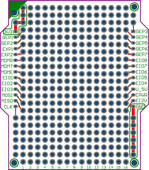
Expansion Port (Prototype PCB)
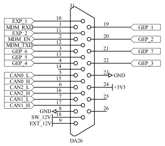
DA26 Connector
Example: to route EIO_8 (port 9) to GEP_7 (pin 21 on the DA26), set a jumper on pins 10+12 on the expansion port.
Commands
EGPIO control is provided by the egpio command set:
egpio output <port> <level> [<port> <level> …]– set output level(s)egpio input <port> [<port> …]– query input level(s)egpio status– show output, input & monitor statusegpio monitor <on|off> [ports]– enable/disable monitoringegpio monitor status– show current monitoring status
To configure a port for input, it needs to be switched to output level high (1). That is done
automatically by the input and monitor commands.
If you set multiple outputs, the ports will be set one at a time, so output levels will change with a slight delay. You can use this behaviour to set data lines before a clock line, e.g. when sending bits serially into a shift register.
Note
The MAX7317 needs active polling to detect input state changes. Monitoring is disabled by default, it can be enabled manually or configured to start automatically on module init. Without monitoring, only manual input queries will update the input state, trigger input events and input metric updates.
Configuration
Parameter |
Instance |
Description |
|---|---|---|
auto |
egpio |
yes = Start monitoring on boot (default: no) |
egpio |
monitor.ports |
List of ports to monitor by default (space separated) |
egpio |
monitor.interval |
Polling interval in milliseconds (min 10, default 50) |
The default interval of 50 ms (= 20 Hz) means an input signal needs to be at least 50 ms long to be detected. This polling frequency produces a CPU load of ~0.5% on core 1 and is normally sufficient to detect even very short button pushes.
Metrics
Metric name |
Example value |
Description |
|---|---|---|
m.egpio.input |
0,1,2,3,4,5,6,7,9 |
EGPIO input port state (ports 0…9, present=high) |
m.egpio.monitor |
8,9 |
EGPIO input monitoring ports |
m.egpio.output |
4,5,6,7,9 |
EGPIO output port state |
Hint: to process these metrics from Javascript, read them into an array using eval()
and test for the presence of a port number using e.g. the includes() method in a browser plugin.
Duktape does not support includes(), you can test indexOf(port) instead.
Example:
var input = eval(OvmsMetrics.AsJSON("m.egpio.input"));
if (input.indexOf(9) < 0)
  print("Input port 9 (EIO8) is currently low\n");
Events
Event |
Data |
Purpose |
|---|---|---|
egpio.input.<port>.<state> |
– |
EGPIO input port change (port=0…9, state=high/low) |
egpio.output.<port>.<state> |
– |
EGPIO output port change (port=0…9, state=high/low) |
Hint: to listen to events from Javascript, bind to msg:event on a .receiver object
from browser context or use PubSub from module context.
Example:
PubSub.subscribe("egpio.input.9.low", function(){
  print("Input port 9 (EIO8) is now low\n");
});